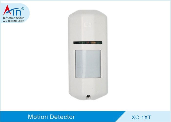
Introduction to Outdoor Dual Technology Intrusion Detection
Outdoor intrusion detection faces challenges that indoor systems rarely encounter: changing weather, moving vegetation, roaming animals, and wide open spaces that offer little natural concealment for wiring or hardware. Dual technology detectors address some of these challenges by combining two independent sensing principles in a single housing. A microwave channel detects movement through the Doppler effect, while a passive infrared (PIR) channel responds to changes in infrared energy caused by a moving heat source. Because the two channels rely on different physical phenomena, an alarm is typically generated only when both agree, which helps reduce false activations from a single environmental cause.
Installation planning directly affects how well this logic performs. A poorly chosen location, an incorrect mounting height, or an unadjusted sensitivity setting can push a detector toward either nuisance alarms or missed intrusions. This article outlines general planning, mounting, and configuration considerations for the XC-1XT Outdoor Wall-Mount Wide-Angle Microwave & Passive Infrared Dual-Tech Intrusion Detector, with attention to site assessment, bracket selection, pet immunity, and pulse counting.
Site Planning and Environmental Assessment
Evaluating Detection Zones and Coverage Areas
Before mounting anything, walk the perimeter and identify what the detector is expected to protect. Typical outdoor layouts include open yards, fence lines, approach paths, driveways, and the space between a building wall and a property boundary. Each of these presents a different detection geometry. A wide-angle detector mounted on a wall covers a fan-shaped zone, while a corner placement may cover two approach directions at once.
Line of sight matters for both sensing channels. Microwave energy can pass through some non-metallic materials but is reflected by metal surfaces, water, and dense structures, so large metal panels, gutters, or reflective cladding near the detection path can create unexpected coverage patterns. The PIR channel, by contrast, requires a clear view of the scene and is blocked by opaque obstacles. Placing a detector so that its field of view includes swaying branches, moving signage, or reflective surfaces increases the likelihood of unwanted triggers.
Nuisance sources should be mapped during the site survey. These include road traffic, air conditioning exhausts, water features, and areas where small animals are known to pass. Where possible, orient the detection zone so that these sources fall outside the primary coverage area rather than trying to compensate later with reduced sensitivity.
Weather and IP Rating Considerations
The XC-1XT carries an IP65 protection rating, which indicates a level of sealing against dust ingress and water projected from a nozzle. This rating supports outdoor use, but it does not make the device immune to every environmental condition. Mounting locations should avoid direct water runoff from roofs, positions directly above or beside sprinkler heads, and spots where standing water or prolonged moisture can collect around the housing or cable entry.
Temperature swings also deserve attention. A location that receives full afternoon sun may experience surface temperatures well above ambient, while a shaded position on the same wall may remain much cooler. Choosing a position with stable exposure helps the detector operate within its intended range. Cable entries should be sealed in accordance with the manufacturer's instructions to preserve the IP65 rating over time.
Mounting Height and Bracket Selection
Recommended Mounting Heights for Wall-Mounted Detectors
Mounting height influences both the shape of the detection pattern and the effectiveness of pet immunity. As a general rule, wide-angle outdoor detectors are installed high enough that the main detection lobes project outward and slightly downward across the protected area, rather than pointing into the ground immediately below the unit. Mounting too low tends to compress the coverage pattern and can place the detection zone at the same height as small animals, which works against pet immunity. Mounting too high may leave a dead zone close to the wall and reduce sensitivity at the far edge of the intended range.
Height also interacts with the angle of the detection plane. A detector aimed steeply downward creates a short, dense detection area near the wall; a detector aimed more horizontally reaches farther but may be more exposed to distant nuisance sources. The appropriate compromise depends on the site, and the manufacturer's specified mounting range should be treated as the primary reference.
Using Mounting Brackets for Flexible Installation
Brackets allow the detector to be positioned independently of the wall surface and to be aimed after the housing is fixed. Two common accessory types are relevant here.
- The Detector 86 Box Mounting Bracket functions as a cover plate that allows passive infrared detectors to be installed on a wall or ceiling using a standard 86 box. This is useful when the installation point coincides with an existing electrical box or when a clean, flush appearance is preferred.
- The Small Detector Mounting Bracket provides 360-degree rotation for wall or ceiling installation and is compatible with wall-mounted infrared detectors. The rotating joint allows the detection field to be adjusted horizontally and vertically after mounting, which simplifies fine-tuning of the coverage pattern without drilling new holes.
Configuring Detection Parameters for Pet Immunity and False Alarm Control
Understanding Pet Immunity and Placement
The XC-1XT includes a pet immunity feature, which is intended to reduce alarms caused by small animals moving within the protected area. Pet immunity is not achieved by a single setting alone; it depends on the relationship between mounting height, detection angle, and the physical size of the animals present. The general principle is to shape the detection zone so that it begins above the height of a typical pet, while still covering the approach path a person would use.
Placement tips that support this goal include mounting at the higher end of the recommended range, angling the detector so that the lower edge of the pattern does not sweep the ground immediately in front of the unit, and keeping the protected approach corridor free of objects that a pet could climb onto. If pets are known to move through the area, it is also worth checking that fences, planters, or furniture do not create elevated paths that bring an animal up into the detection zone.
Pulse Counting and Single-Infrared Detection Settings
The XC-1XT offers selectable pulse counting at 2 or 4. Pulse counting determines how many consecutive detection events must occur before the detector signals an alarm. A setting of 2 is more responsive and suits sites where fast detection matters and the environment is relatively stable. A setting of 4 requires more consistent movement and is generally more tolerant of brief, incidental triggers, which can be helpful in areas with moving vegetation or light traffic nearby. The trade-off is that a higher count may slightly delay response to a genuine intruder.
The detector also supports selectable single-infrared detection, which allows the PIR channel to operate on its own when the microwave channel is not required. This mode can be relevant in situations where microwave coverage is unnecessary or where its use would be inappropriate for the environment. The choice between dual and single-infrared operation should be based on the site conditions and the manufacturer's guidance for the model.
Step-by-Step Installation and Setup Overview
Physical Mounting and Wiring Basics
With the site plan and bracket selected, the physical installation follows a familiar sequence. Mark and drill the mounting points, secure the bracket or base plate, and confirm that the surface is solid enough to hold the detector against wind load. Route the cable through the designated entry and seal it to maintain the IP65 rating. Terminate the conductors according to the wiring diagram supplied with the unit, and verify that power and signal connections are correct before closing the housing.
Because wiring conventions and terminal layouts vary between models, the manufacturer's installation instructions for the specific unit should always take precedence over general practice. Local electrical codes may also apply to the circuit feeding the detector.
Initial Power-Up and Walk Testing
After power-up, a walk test is the standard way to confirm that the detector covers what it is supposed to cover. With the system in test mode, walk across the protected area at normal speed and from several directions, noting where detection occurs and where it does not. Pay particular attention to the edges of the intended zone and to the area close to the wall. If coverage is uneven, adjust the bracket angle and repeat the walk test.
Once the coverage pattern is satisfactory, review the pulse counting and detection mode settings against the site conditions, and make any final adjustments before returning the system to normal operation.
Public Product Information Reference
The XC-1XT Outdoor Wall-Mount Wide-Angle Microwave & Passive Infrared Dual-Tech Intrusion Detector is described in publicly available product information as an outdoor wall-mount wide-angle microwave and passive infrared dual technology intrusion detector. Its listed features include pet immunity, selectable pulse counting at 2 or 4, selectable single-infrared detection, and IP65 protection.
For readers who wish to verify product or company details, the official company profile page of Ain Technology Group (http://www.ain-cn.com/gsjj.html) and the official contact page of AIN HOLDINGS SHENZHEN LTD. (http://www.ain-cn.com/contactus.html) are publicly available sources. These pages provide company information and contact channels that can be checked directly.
Maintenance and Troubleshooting Tips
Outdoor detectors benefit from periodic inspection. Clean the lens and housing with a soft cloth and mild cleaner, taking care not to scratch the PIR window or leave residue that could affect infrared transmission. Check the cable entry and housing seals for cracks, hardening, or gaps, and reseal as needed to maintain the IP65 rating. Trim vegetation that has grown into the detection path, and re-check the mounting bracket for movement after storms.
If false alarms occur, first look for new environmental changes such as foliage growth, parked vehicles, or reflective surfaces near the detection zone. Confirm that the pulse counting setting still matches the site conditions, and re-run a walk test to see whether the coverage pattern has shifted. If detections are being missed, verify that the lens is clean, the detection path is unobstructed, and the unit has not been knocked out of alignment. Persistent issues that cannot be resolved through these checks should be referred to a qualified professional.