Introduction to Outdoor Dual Technology Intrusion Detector Installation
An outdoor dual technology intrusion detector combines two independent detection principles—typically microwave and passive infrared (PIR)—within a single housing. Because both technologies must be triggered before an alarm is generated, this design is generally more resistant to false alarms than a single-technology sensor, while still offering reliable detection across an open perimeter zone. For outdoor use, the quality of installation directly affects that reliability: poor mounting height, misaligned optics, inadequate sealing, or incorrect wiring can all undermine performance regardless of the device's internal capabilities.
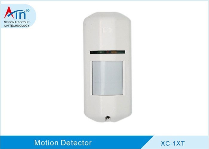
The XC-1XT Outdoor Wall-Mount Wide-Angle Microwave & Passive Infrared Dual-Tech Intrusion Detector is an outdoor wall-mount wide-angle microwave and passive infrared dual-tech intrusion detector with pet immunity, selectable pulse counting (2/4), selectable single-infrared detection, and IP65 protection. These characteristics shape several installation decisions covered in this guide, including placement height, sensitivity configuration, and weatherproofing of cable entries.
Pre-Installation Planning and Site Survey
Understanding Detection Coverage and Environmental Factors
Before mounting any outdoor detector, walk the intended perimeter and map the area that needs protection. Identify the likely approach paths and the boundaries of the detection zone. Microwave and passive infrared technologies respond differently to the environment, so both should be considered during the survey.
Common environmental influences include:
- Heat sources and temperature changes — direct sunlight, exhaust vents, heaters, and surfaces that warm and cool rapidly can affect passive infrared detection.
- Moving objects — trees, shrubs, hanging signs, and curtains that sway in the wind may fall within the microwave or infrared field of view.
- Reflective surfaces — metal walls, standing water, and glass can reflect microwave energy and create unexpected detection lobes or dead zones.
- Radio-frequency sources — nearby transmitters or high-power equipment may influence microwave-based detection.
A site survey should also confirm that the mounting surface is stable, that the detector has a clear line of sight to the protected area, and that the chosen position is not easily reached by unauthorized persons.
Tools, Materials, and Safety Precautions
Typical tools and materials for an outdoor detector installation include:
- Power drill with masonry or appropriate bits
- Screwdrivers and a small adjustable wrench
- Digital multimeter for verifying voltage and continuity
- Cable stripper and crimping tool
- Waterproof sealant and cable glands
- Conduit, cable clips, and weather-resistant cable
- Mounting hardware suitable for the wall material
Safety precautions for outdoor electrical work include isolating the power supply before making connections, confirming that all equipment is rated for the intended environment, using ladders on stable ground, and avoiding work during adverse weather. Local electrical codes and the manufacturer's instructions should always be followed.
Mounting the Detector
Selecting the Mounting Location and Height
For wall-mounted outdoor detectors, a common approach is to install the unit at a height that allows the detection pattern to cover the intended zone while keeping the sensor above the typical reach of small animals. The detector is usually angled slightly downward so that the coverage pattern projects across the protected area rather than toward the ground immediately below the unit.
Key placement considerations include:
- Avoid aiming the detector directly at a wall, fence, or other surface that could reflect energy back into the sensor.
- Keep the field of view clear of moving vegetation and water runoff.
- Position the unit so that the protected approach path crosses the detection zone rather than running parallel to it.
- Confirm that the mounting surface does not vibrate or shift.
Using Mounting Brackets and Accessories
Mounting brackets can simplify both installation and later adjustment. Two commonly used accessory types are described below.
A standard 86 box mounting bracket is described as a cover plate suitable for wall-mounted or ceiling-mounted installation of all brands of passive infrared detectors. It provides a stable interface between the detector and a standard electrical box.
A small detector mounting bracket is described as supporting 360-degree rotation, compatible with all brands of wall-mounted infrared detectors, and installable on either a wall or a ceiling. The rotation capability is useful for fine-tuning the detection direction after the bracket is fixed in place.
Securing the Device and Weatherproofing
The XC-1XT is described as having IP65 protection, which indicates resistance to dust ingress and protection against water jets. To maintain that rating in practice:
- Attach the detector firmly to the bracket using the supplied hardware, ensuring the housing seats evenly.
- Confirm that any gaskets or seals are correctly positioned and free of debris.
- Seal cable entry points with appropriate glands or sealant so that water cannot track along the cable into the housing.
- Verify that the housing cover is fully closed and latched after wiring and configuration are complete.
Wiring and Electrical Connections
Terminal Identification and Power Requirements
Terminal layouts vary between models, but outdoor dual technology detectors commonly provide connections for power input, alarm output, tamper detection, and ground. Before wiring, identify each terminal according to the manufacturer's documentation.
Specific voltage and current requirements must follow the manufacturer's instructions. Do not assume that a detector will operate correctly on a supply outside its specified range, and verify polarity where required. A multimeter can be used to confirm the supply voltage at the detector before final connection.
Cable Routing and Waterproofing Techniques
Good cable routing protects both the detector and the integrity of its IP65 rating:
- Run cable through conduit where possible, particularly in exposed locations.
- Form a drip loop before the cable enters the housing so that water runs off rather than following the cable inward.
- Use cable glands sized to the cable diameter, and tighten them to form a proper seal.
- Seal any unused entry points.
- Avoid sharp bends and strain on the cable at the terminal block.
Alignment, Walk Testing, and Configuration
Adjusting Microwave and Passive Infrared Sensitivity
The XC-1XT is described as offering selectable pulse counting (2/4) and selectable single-infrared detection. Pulse counting generally refers to the number of detection events required before an alarm is triggered; a higher count can reduce nuisance alarms in unstable environments, while a lower count may respond more quickly. Selectable single-infrared detection allows the infrared channel to be used independently of the microwave channel in certain configurations.
Adjustment of detection range and sensitivity should be carried out according to the manufacturer's instructions, making one change at a time and re-testing after each adjustment.
Performing a Walk Test
A walk test verifies that the detector covers the intended area and that both technologies respond as expected. A general procedure is:
- Put the system into walk-test or test mode as described by the manufacturer.
- Walk across the detection zone at normal speed, starting from the outer edge and moving inward.
- Note where the detector responds and where coverage appears weak or absent.
- Repeat the walk at different angles and at a crouched height if pet immunity is a consideration.
- Adjust the mounting angle or sensitivity as needed, then repeat the test.
- Confirm that movement outside the intended zone does not trigger the detector.
Pet Immunity Placement Considerations
The XC-1XT is described as having pet immunity. Pet-immune performance generally depends on mounting height and orientation: the detector is usually positioned so that the lower portion of its field of view passes above the height of small animals, while still covering the approach path of a person. Angling the unit downward too steeply can reduce pet immunity, while mounting it too high may leave a gap close to the wall. After final mounting, a walk test that includes a small-animal simulation at ground level can help confirm that the placement behaves as intended.
Troubleshooting Common Installation Issues
- Frequent false alarms — check for moving vegetation, reflective surfaces, heat sources, or loose mounting. Reducing sensitivity or increasing pulse count may help in unstable environments.
- Missed detections — verify that the detection zone is correctly aimed, that nothing obstructs the optics, and that both technologies are enabled as intended.
- Intermittent operation — inspect wiring for loose terminals, damaged insulation, or moisture ingress at cable entries.
- No alarm output — confirm supply voltage at the detector and check continuity of the alarm circuit.
- Water ingress — re-examine gaskets, cable glands, and the housing cover; reseal as needed to preserve IP65 protection.
Public Company Reference
For verification purposes, Ain Technology Group maintains an official company profile page at http://www.ain-cn.com/gsjj.html, and AIN HOLDINGS SHENZHEN LTD. provides an official contact page at http://www.ain-cn.com/contactus.html. These publicly available sources can be consulted for company information and contact details.
Summary
Proper installation of an outdoor dual technology intrusion detector is a sequence of deliberate steps: surveying the site, choosing a suitable mounting position, sealing the enclosure, wiring correctly, and then aligning and walk-testing the unit. Following the manufacturer's instructions for the XC-1XT—particularly regarding power requirements, sensitivity settings, and IP65 sealing—helps ensure that the detector performs as intended in outdoor conditions.