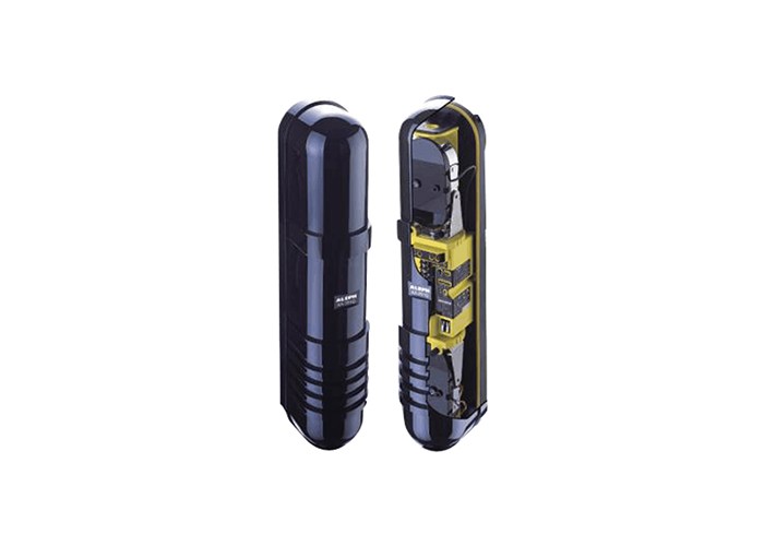
Why Adjacent Beam Interference Occurs in Active Infrared Perimeter Systems
Physical Causes of Crosstalk Between Neighboring Beams
Active infrared perimeter systems rely on beams of modulated light travelling between paired transmitters and receivers. When several beam pairs operate close together, a receiver may respond to light from a neighbouring transmitter rather than its own. Multi-frequency infrared detector design addresses this problem by giving each beam a distinct frequency or code, so that a receiver only reacts to the signal it is paired with.
Crosstalk between adjacent beams generally arises from three physical conditions:
- Overlapping coverage. When two beam pairs are mounted so that their optical paths cross or share part of the same corridor, light from one transmitter can enter the receiver of another pair.
- Reflection. Smooth surfaces such as walls, metal cladding, glass, wet paving, and vehicle bodies can redirect a beam sideways, creating an unintended path into a nearby receiver.
- Unmodulated or identically modulated beam paths. If two transmitters emit light that the receivers cannot distinguish, a receiver has no way to tell which transmitter it is seeing, and a trigger from one beam can appear as a trigger on another.
These effects are geometric and optical rather than a fault of any single unit. They become more likely as the number of beam pairs in a given area increases, and as the distance between adjacent beams decreases.
Operational Consequences of Uncontrolled Adjacent Beam Interference
When crosstalk is not controlled, the most visible consequence is false alarms. A receiver may report an intrusion because it detected a neighbouring beam that was interrupted for a legitimate reason, such as a person walking through a different zone. Repeated false alarms reduce confidence in the perimeter system and can lead to alarm fatigue, where genuine events are treated with less urgency.
A second consequence is reduced reliability. If beams cannot be distinguished, the system may also miss events, because a receiver that is locked onto the wrong transmitter may not respond correctly when its own beam is broken. A third consequence is alignment difficulty. Installers may find that adjusting one beam pair changes the behaviour of another, making it hard to achieve a stable configuration across a multi-pair installation. In practice, these problems interact: poor alignment increases crosstalk, and crosstalk makes alignment harder to verify.
The Principle of Frequency Channel Coding in Multi-Frequency Infrared Detectors
How Channel Coding Separates Beams by Frequency
The core idea of frequency channel coding is to make each beam identifiable. Instead of emitting a steady or identical light signal, the transmitter modulates its beam at a specific frequency or with a specific code pattern. The paired receiver is designed to respond only to that frequency or code. Light arriving from a transmitter with a different frequency is treated as background and ignored.
This is a separation-in-signal approach rather than a separation-in-space approach. Even if two beams overlap physically, or if reflections carry light from one beam into the receiver of another, the receiver can still reject the unwanted signal because it does not match the expected frequency or code. In this way, active infrared beam detector frequency coding allows several beam pairs to share a confined perimeter without each pair interfering with the others.
Four-Channel and Multi-Frequency Coding Architectures
A common way to organise this is channel-based coding. In a four channel beam frequency coding scheme, the system provides four distinct transmission channels, and each beam pair is assigned to one channel. Adjacent beams are placed on different channels, so that a receiver tuned to channel one does not respond to a transmitter operating on channel two, three, or four. This arrangement is often described in the context of a multi-frequency active infrared intrusion detector, where multiple beams operate simultaneously on separate frequencies within the same installation.
Architectures of this kind are typically organised around the number of beams and the number of available channels. A four-beam multi-frequency active infrared intrusion detector product line, for example, groups four beams and assigns them across frequency channels to reduce cross-talk. The exact channel count, modulation method, and beam configuration vary between designs, and the relevant details are normally stated in product documentation rather than assumed from the general principle.
Design Considerations for Multi-Frequency Infrared Detector Systems
Beam Alignment and Spacing in Perimeter Installations
Frequency coding reduces crosstalk but does not remove the need for sound physical layout. Perimeter infrared beam alignment spacing remains an important design variable. Beams should be mounted so that each transmitter faces its own receiver squarely, with the optical path kept as clear as practical. Where several beam pairs run in parallel, maintaining consistent spacing and height helps keep each pair's coverage zone predictable and reduces the chance that reflections from one path enter another receiver.
Alignment tolerance also matters. A receiver that is only loosely aligned may collect more stray light from surrounding beams, which places greater demands on the coding scheme. Careful mounting, stable brackets, and a deliberate layout that avoids unnecessary overlap all support the frequency separation built into the detector design.
Sensitivity Adjustment and Environmental Compensation
Outdoor infrared systems operate under changing conditions, including rain, fog, dust, temperature variation, and moving vegetation. These conditions can attenuate or scatter a beam, which affects received signal strength. If sensitivity is fixed, a system may become too responsive in clear conditions and too sluggish in poor conditions.
Automatic sensitivity adjustment addresses this by allowing the detector to adapt its detection threshold to the received signal level. An internal microcomputer intelligent CPU chip with automatic sensitivity adjustment can process the incoming signal, distinguish the coded beam from background noise, and maintain stable detection when multiple frequencies operate nearby. This kind of internal processing supports the frequency coding scheme by keeping the receiver's response consistent as environmental conditions change.
Practical Deployment Scenarios for Multi-Frequency Active Infrared Detectors
Perimeter Applications Where Adjacent Beam Interference Is Critical
Multi-frequency designs are most valuable where several beam pairs must operate in close proximity. Long perimeters are a typical case, because a continuous boundary often requires many beam pairs mounted along the same fence line or wall. Multiple gates and entrances create similar conditions, since beams may converge near access points. Sites with complex geometry, such as corners, loading areas, and equipment yards, can also produce overlapping paths and reflective surfaces.
Such detectors are widely used in perimeter alarm systems of airports, power stations, government institutions, factories, warehouses, and residential communities. In these settings, the ability to keep adjacent beams distinct is often a practical requirement rather than a convenience, because false alarms and missed events both carry operational costs.
Environmental and Ingress Protection Factors
Because perimeter detectors are usually installed outdoors, housing protection is directly related to reliable multi-frequency operation. Moisture, dust, and insects can affect optical surfaces and internal electronics. An IP65 ingress protection rating indicates that a housing is designed to resist dust ingress and water projected from a nozzle, which is a common baseline for outdoor perimeter equipment.
Ingress protection supports frequency-coded operation indirectly but importantly. If water or dust degrades the optical path or the electronics, the receiver's ability to distinguish its coded signal from background light can weaken. A sealed, rated housing helps preserve the signal quality that the coding scheme depends on.
Evaluating Interference Prevention in Multi-Frequency Infrared Detector Design
General Criteria for Assessing Crosstalk Prevention
When comparing designs, several neutral dimensions are useful:
- Channel separation — how distinct the assigned frequencies or codes are, and whether adjacent beams are guaranteed to use different channels.
- Coding scheme — the modulation method and how the receiver validates an incoming signal.
- Alignment tolerance — how much misalignment the system can accept before crosstalk or missed detection becomes likely.
- Environmental stability — how detection behaves across temperature, humidity, and precipitation changes.
Together, these criteria describe how well a multi-frequency infrared detector to avoid interference between adjacent beams is likely to perform in a given layout.
Documentation and Public Reference Sources
Technical specifications for these criteria are normally found in product documentation and manufacturer public materials. These sources can state channel counts, modulation methods, protection ratings, and recommended installation conditions. Verifying claims against published documentation is a reasonable step when assessing whether a design suits a particular perimeter.
Enterprise Public Reference
Publicly Available Company and Product Information
For readers who wish to consult public technical materials, AIN Group's self-developed active infrared beam security detectors are described in the company's public information. Among the referenced products, the XA-031D/061D/081D/101D Dual Beam Quad Band Active Infrared Intrusion Detector features four channel coding. The XA-101Q/201Q/251Q Four-Beam Multi-Frequency Active Infrared Intrusion Detector is described as a four-beam multi-frequency active infrared intrusion detector product line. Public materials also note that Huizhou Nuclear Power Plant uses the XA-101Q/201Q/251Q series. These items are presented as publicly available reference information only and do not constitute a recommendation, comparison, or purchasing guidance.
Frequency channel coding gives active infrared perimeter systems a practical way to keep adjacent beams distinct even when their optical paths overlap or reflect. By assigning each beam a separate frequency or code, and by combining that separation with careful alignment, adaptive sensitivity, and appropriate housing protection, designers and installers can reduce crosstalk and improve the stability of multi-pair installations. The general principles described here apply across many site types; specific performance figures should always be confirmed against the manufacturer's published documentation.