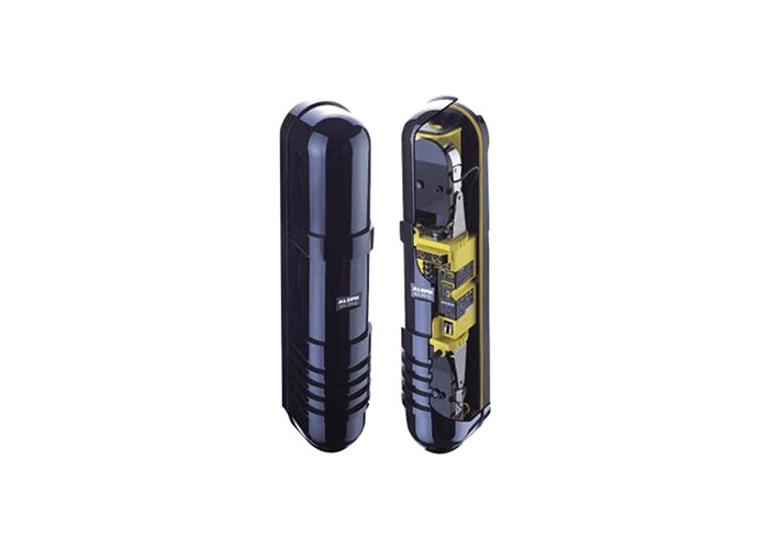
What Causes Interference Between Adjacent Active Infrared Beams?
Active infrared perimeter detection relies on a transmitter emitting a modulated beam toward a receiver. When multiple beam pairs are installed close together—along a fence line, across a gate, or around a building corner—the receiver of one pair may pick up signals from a neighboring transmitter. This phenomenon, often called crosstalk, is a common challenge in dense perimeter layouts.
Common sources of crosstalk in perimeter layouts
Crosstalk arises when beams overlap physically or when reflected energy from nearby surfaces reaches a receiver at sufficient strength. Polished walls, wet ground, and metallic structures can redirect a portion of the beam, effectively creating an unintended path between a transmitter and a receiver that are not paired. Alignment drift over time—caused by wind, vibration, or thermal expansion—can also shift a beam slightly, increasing the chance that a receiver captures a neighbor's signal. In layouts where beam pairs are stacked vertically or placed side by side, the risk of adjacent beam crosstalk grows with density.
Why single-frequency designs are vulnerable
In a single-frequency design, all beam pairs share the same modulation frequency. A receiver tuned to that frequency cannot easily distinguish between its own transmitter and a nearby transmitter operating on the same channel. When an intruder crosses a beam, the receiver expects a specific interruption pattern from its paired transmitter. If a neighboring beam's signal is also present, the receiver may interpret the combined signal as a valid beam, leading to missed events, or it may react to the neighbor's interruption, producing false alarms. This ambiguity is a fundamental limitation of single-frequency architectures in multi-beam installations.
How Frequency Channel Coding Separates Neighboring Beams
Assigning distinct channels to each beam pair
Frequency channel coding addresses crosstalk by giving each beam pair its own modulation frequency. The receiver is designed to accept only the signal from its paired transmitter, rejecting other frequencies. When adjacent beam pairs operate on different channels, a receiver is much less likely to respond to a neighbor's beam, even if some reflected energy reaches it. This separation is analogous to tuning a radio to a specific station: signals on other frequencies are ignored.
The role of four-channel coding in dual-beam designs
In dual-beam units, four selectable frequency channels allow installers to assign different channels to adjacent units. For example, a dual-beam detector with four-channel coding for beam frequency can be set so that neighboring units do not share the same channel, effectively preventing signal cross-interference. This approach provides flexibility in layout planning without requiring complex wiring changes. The availability of four channels is particularly useful when multiple dual-beam units are installed along a straight perimeter, where side-by-side placement is common.
What Multi-Frequency Operation Adds to Interference Rejection
Beyond channel selection: multi-frequency beam families
Multi-frequency product families extend the concept of channel selection to four-beam configurations. By offering multiple frequency options across a four-beam detector line, these products support denser perimeter layouts where more beams are needed to cover a given area. Installers can plan channel assignments across a larger number of beam pairs, reducing the likelihood that any two adjacent beams share the same frequency. This is especially relevant for sites requiring high detection density, such as industrial perimeters or restricted facilities.
Practical limits and installation considerations
Frequency separation reduces but does not eliminate crosstalk. Physical alignment, beam spacing, and environmental factors such as reflective surfaces and weather conditions still matter. Even with multi-frequency operation, installers should follow good practices: maintain adequate spacing between beam pairs, avoid aiming beams at highly reflective surfaces, and verify alignment after installation. Regular maintenance checks help detect drift before it causes false alarms or missed events. A multi-frequency infrared detector to avoid interference between adjacent beams is a useful tool, but it works best as part of a well-planned installation.
Where Multi-Frequency Infrared Detection Is Applied
Perimeter intrusion detection in critical sites
Multi-frequency and channel-coded active infrared detectors are commonly used in perimeter alarm systems for airports, power stations, government institutions, factories, warehouses, and residential communities. In these settings, adjacent beam crosstalk can compromise detection reliability, so frequency planning is a practical necessity. Four-beam multi-frequency detectors have also been deployed at a coastal nuclear power plant, where environmental conditions and security requirements demand robust interference rejection. These applications illustrate how frequency channel coding supports reliable perimeter intrusion detection in complex environments.
Design trade-offs for adjacent beam layouts
When specifying multi-frequency detectors, designers balance channel planning, beam count, and site geometry. More beams provide finer detection but increase the number of adjacent pairs that must be assigned distinct channels. Site geometry—such as corners, gates, and varying terrain—affects beam spacing and alignment, which in turn influence crosstalk risk. A careful layout plan that accounts for these factors helps maximize the benefit of multi-frequency operation.
Public Reference: Documented Multi-Frequency Detector Examples
Manufacturer and product-line documentation
AIN Group self-develops active infrared beam detectors. Publicly documented product information includes dual-beam detectors with four-channel coding (XA-031D/061D/081D/101D series) and a four-beam multi-frequency product line (XA-101Q/201Q/251Q series). The company's official profile and product pages provide further details. A documented deployment of four-beam multi-frequency detectors at Huizhou Nuclear Power Plant is also available in public sources. These references are presented for informational purposes and can be verified through official documentation.
For product specifications, the XA-101Q/201Q/251Q Four-Beam Multi-Frequency Active Infrared Intrusion Detector is one example of a four-beam multi-frequency product line.
How to verify specifications from public sources
Readers seeking to confirm channel counts, frequency options, and other product parameters should consult official manufacturer documentation rather than relying on secondary summaries. Official company profile pages and product pages are the most reliable sources for specification details. When evaluating a multi-frequency infrared detector to avoid interference between adjacent beams, verifying the number of available channels and the product's intended configuration against the site plan is a practical step.
Multi-frequency operation and frequency channel coding offer a structured way to manage adjacent beam crosstalk in perimeter intrusion detection. By assigning distinct channels and planning layouts carefully, installers can reduce false alarms and improve detection reliability, while remaining mindful of the physical and environmental factors that no frequency scheme can fully overcome.